1.2. STATE-OF-THE-ART
Additive manufacturing technologies have been a game changer in enabling the fabrication of ultra strong but lightweight parts and while FDM has made incredible strides in architecture in the past decade in terms of accuracy, material deposition and part creation. The increased interest in infill design and bespoke fabrication of 3D printed structures has provided a few projects that showcase the potential of curating toolpaths for architectural elements.
While freeform wall design strategies are being addressed with conventional fabrication strategies, additive manufacturing provides a process of developing more complex shapes and geometric freedom in design by allowing for the mass adoption of complex shapes at an economical value. For example, binder jet 3D printing (BJP) was used for production of a lightweight concrete slab in Smart Slab allowing for structural layout and minimizing material by taking care of the overall geometry of the slab (Aghaei Meibodi et al 2018), FDM being used for printing of large scale functionally-graded facade by looking at the optimization of the infill (Taseva at el 2020), and finite element analysis to influence infill generation of 3D printed parts (Borunda 2019).These projects examine how additive manufacturing can solve issues of functional internal layers that is a developing topic of additive manufacturing architectural solutions. Taking a critical look at where the best possible solutions for internal mechanics as well as combining that with an optimized internal structure has the possibility to expand the uniqueness of the geometrical forms that are possible.
This research explores a method of integrating the functionally designed infill with the use of novel computational methods to predict the possible fabrication solutions. While building off the work that the original pix2pix paper (Isola, Phillip, et al 2018) explores and how the process can be leveraged for architectural fabrication.
2. FDM infill
Increased interest in 3d printing thermoplastics have exploded over the past decade but there are still gaps when discussing 3D printing infill and infill optimization. What this research means to identify is how one can expand from typical infill patterns as shown in figure 1 to bespoke patterns that increase wall efficiency and finds localized solutions to load conditions.
Infill tends to be overlooked when developing geometry due to slicing softwares having pre-baked infills in their software. Infill is intersected with integral computation. Thus, through computation, we can now generate such detailing based on a function such as a load case, and because of 3d printing we can now create such a resolution. By providing an optimisation process that can meet these constraints will lead to further democratization of the design process by enabling human-machine co-creation, where the designer focuses on the external geometry and the machine focuses on the internal geometry (Gopsill 2017). Slicing softwares that are commercially available e.g. Simplify 3D, Cura, Slicer. Allow for custom settings and variable density configurations when setting up the toolpathing by giving the designer the ability to change the density of the layers manually. This technique leaves the printed part at a disadvantage by creating a discontinued toolpath resulting in fragile infill that has only slight adherence to the previous layer. (Borunda et al. 2019)
PathGAN is an ongoing research that focuses on developing a design method which employs machine learning (ML) to generate functionally graded Infill patterns for geometry complex parts in relation to the structural load to be carried by the part. The generated Infill patterns are the micro structure and shape of the material inside of a part. This will enable an increase in the structural strength of the parts while minimizing material consumption. Furthermore, the generation of the infill patterns through ML will be in respect with fused deposition modeling(FDM) fabrication constraints to enable a continuous 3d printing of parts with both large-scale robotic arm and cartesian based printers. This process is achieved through Image to image translation using convolutional neural networks(CNNs) and generative adversarial networks(GANs) to train the information extracted from the finite element analysis (FEA) model based on a colored mapped section to a toolpath represented by the density of the internal structure of the printed part. This resulting in a functionally graded 3d printed architectural wall that conforms to the load requirements while optimizing material usage.
3. Finite Element Analysis and Generative Adversarial Networks
With the ability to analyze a geometry using Finite Element Analysis we can increase the strength-to-weight ability of the part (Gopsill 2017) This is beneficial for wall construction because we can test load cases with planar stress profiles (Gopsill 2017). Our research explores the ability to train the different FEA load cases and the expected outcome of each condition based on the color and the density represented in the color from a 2D section profile and training the FEA analysis in a GAN to output a functionally graded toolpath built for bespoke walls. This research looks to develop a method of predicting the best possible solution for the given load case using neural networks. Previous research has shown that GANs profive a successful platform to predict complex elements in architecture, such as the layout of floor plans based on the input geometry given in a three step process to develop floor plans for an apartment building training from a database of 800+ plans of apartments to color code program. (Chaillou 2019)
This work-in-progress paper describes a novel method of generating a toolpath from load conditions. From FEA analysis to predicted toolpath this research looks to explore the workflow of combining the two methods into one streamlined process. Discussing a proposed process of generating different wall geometric configurations and building a GAN to identify the optimal 3d printing toolpathing for the given input FEA analysis.
Current methods of generating infill include using a slicing software for desktop printers, as described previously, and developing a custom g-code infill using parametric softwares. Infills are typically defined by a pattern input with a defined uniform infill density. Variable densities are not a smart task built into most slicers and libraries. Slicers are usually defined by; pattern, base angle, spacing, and rotation. With the spacing being a static input. The limitation of developing a variable infill is that like the exterior, the pattern/form needs to be designed to account for the amount of layers within the print accounting for overall_height/layer_thickness. While the interior structure is less about the quality of the finish and more about the ability to produce clean exterior shells and providing support for the exterior shells.
The gaps in developing infill is the ability to develop functionally graded infill and being able to dictate the best possible location to add infill at different densities in respect with the structural load. With infill being wasteful from a printing viewpoint the ability to strategize where to add infill and where to not add infill will not only save material but save weight and time. This research is exploring the use of developing infill as a structural aid as well as development of cleaner more complex shape development.
The research explores methods that are applicable to both continuous and noncontinuous toolpaths. The goal is to be able to optimize the path for openings such as fenestrations and the necessary support needed within opening with locations for embeds for architectural assembly.
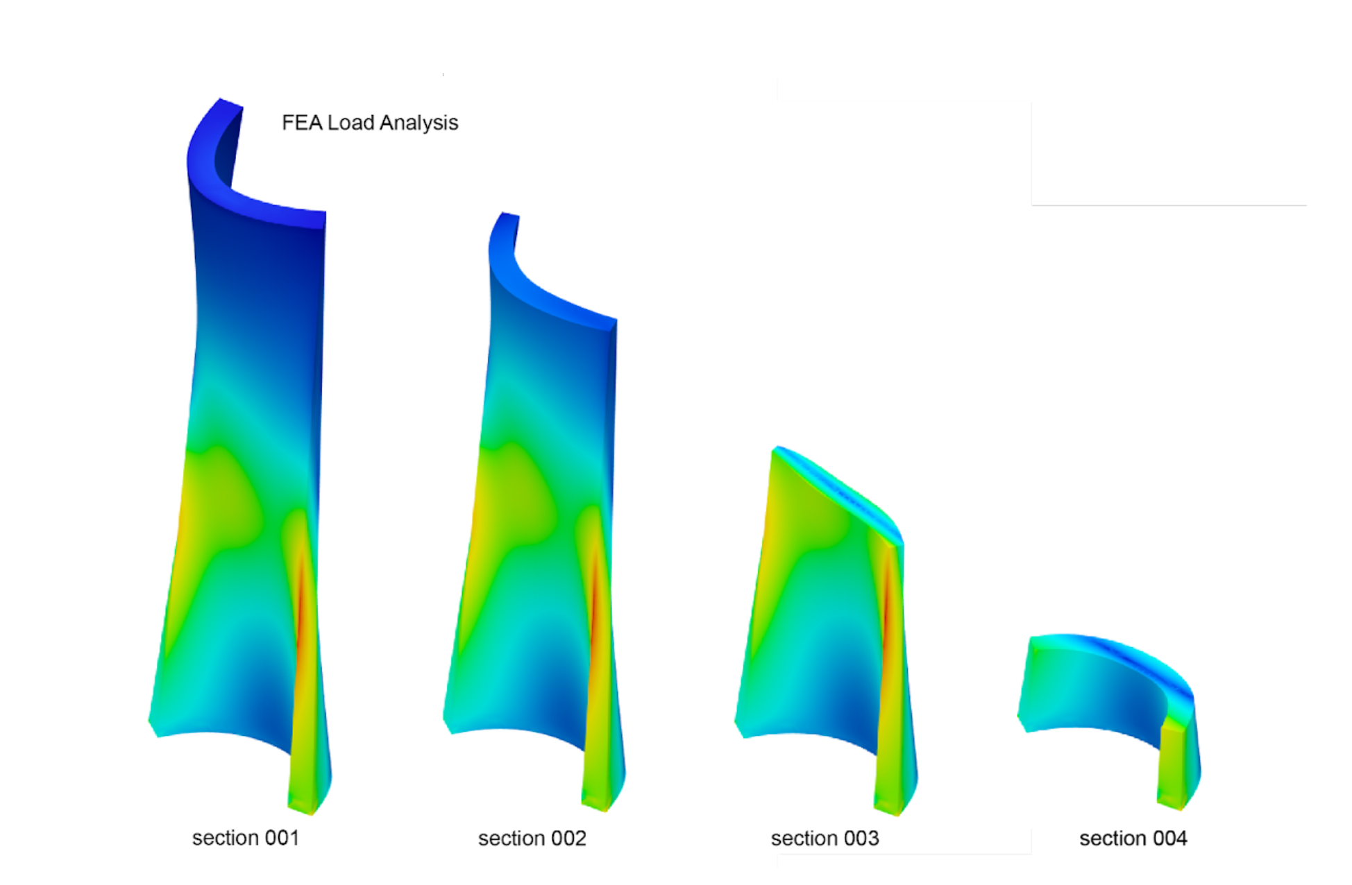
Our proposed method for generating functionally graded infill is based on predicting the density needed within the part by using input from a structural cross section map. This data was obtained by using a FEA analysis in fusion 360. From this mapping of the structural performance of the wall, floor, etc under its dead load. The extracted isolated sections from the object to use as an input for the predicted toolpath using a generative adversarial network (GAN) as the chosen method.
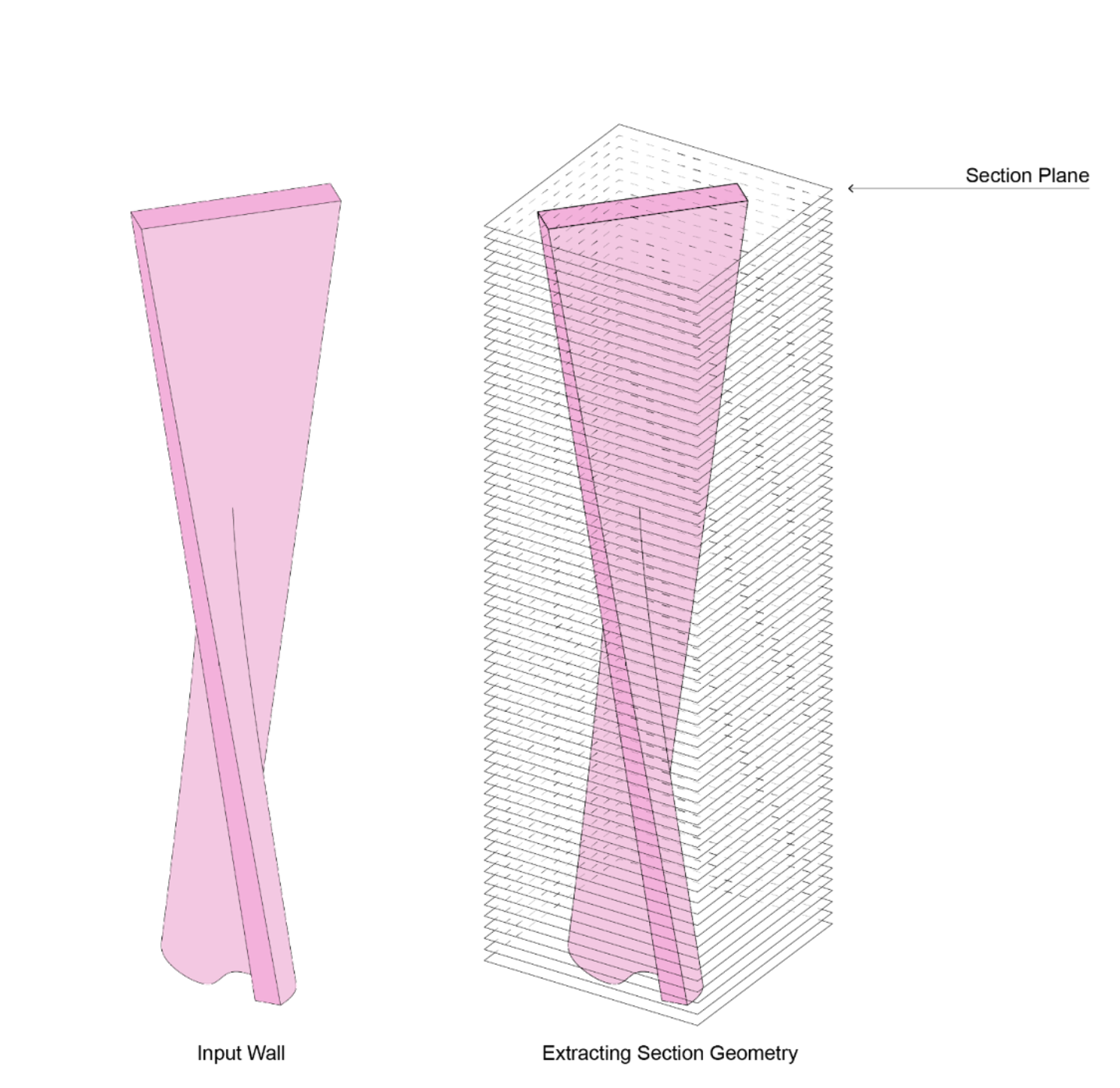
This methodology includes a three part system; training the data on a toolpath geometry that identifies boundary conditions as well as interior structure based on the color input. The second taking the wall and applying the FEA analysis and extracting the cross-sectional profiles at crucial intersections, and lastly using the FEA to predict the functionally-graded toolpath.
Using GANs as the machine learning method that is used to explore image to tool-path. We have found it successful to use pix2pix architecture as the basis of the development within Tensorflow.
The main goal being, translating a represented color as a functional density based on load or thermal qualities, therefore embedding a performance into the wall that also translates directly into fabricatable data. The research intention is to predict the optimal toolpath from a raster image to a vector output. An image to image translation gives us the opportunity to explore whether this endeavor is worthy of development.
These rastered images will be the input for the trained model to output predicted toolpaths. Our most successful current model was trained on 4000 images generated from 8 unique walls The need for more data is still apparent and currently being added to produce better results.
Shown in figure 5 the predicted output from the trained model showcases a successful translation from the input image map to the predicted toolpath. A key feature of having a trained model for the creation of fabrication data is the ability to explore the latent space. This space acts as a sort of morphing state when translating between input maps, generating a prediction output defined by the steps between the inputs as a vector. With this method, our ability to streamline the tool-path layer generation is increased exponentially with generating each layer of the additive manufacturing tool-path as a step within the latent space. Depending on the height between the two input maps will dictate the steps that will need to be traversed between the maps.
The printing path we generate from the GAN model is present in pixel-based format; therefore, we need another module to translate the pixel into vectors and structure in the printing order. There are two steps in the pixel to vector module. First, extract the line profile on each image into the coordinates, and run the path planning algorithm to sort the points. Once we have the structured data, we can send the printing path to the robot and execute the task. Since the data we extract from the image is not the clean line, to avoid the noise data affecting the printing process, we have to do the noise sampling and reconstruct the missing section. Second, merge the data extract from each layer. In this project, each image contains a layer of the path. We need to run a script to track the ending position of each layer and plan the logical way to connect the printing path along the z-axis. Therefore giving us a clean line that can be translated into a toolpath to be used for printing.
Result
Currently, the results are showing a promising development in the prediction of toolpathing for walls. While the results showcase anomalies and disconnected lines, the relationship between the color and density of the predicted toolpath is promising. As the work continues, the dataset will grow to create more accurate predictions for more integrated 3d printed parts based on load conditions.
Conclusion
The proposed method using a GAN showcases the possibility to do all the work upfront to generate data based on the conditions of a typical typology or geometry by leveraging the existing models that a firm generates or by modeling new walls that would satisfy unique conditions. By generating this data once, the model can learn from the elements and predict what needs to happen in areas of similar geometry that increases the time of generating functionally graded infill based on an FEA input. While the focus has been on the digital aspect, the next phase of the project is developing the physical test for large-scale production and testing the validity of the process on large-scale components.


